Table of Contents
Introduction
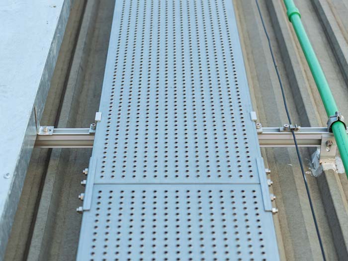
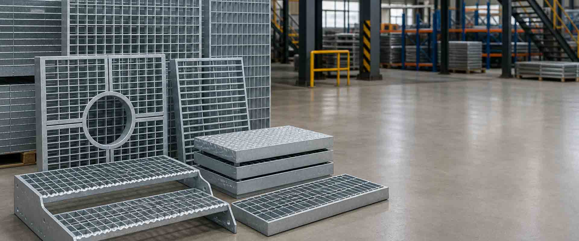
Steel grating specifications determine far more than the outside dimensions of a panel. A complete specification needs to describe how the grating carries loads, how large the openings are, how the panel fits the supporting structure, what surface condition is required, and how fabrication details should be coordinated with the final installation.
Bearing bar depth and thickness, bearing bar spacing, cross bar spacing, clear span, panel dimensions, material, surface configuration, edge treatment, cutouts, and fixing requirements can all influence the finished system.
This is particularly important in industrial applications because two grating panels with the same overall length and width may perform very differently when their internal bar configuration or support conditions change.
For engineers, contractors, and project teams, a clear specification provides a common technical reference before fabrication begins. The following ten details are among the most important items to define when developing steel grating specifications for platforms, walkways, drainage systems, stair structures, and equipment-access applications.
What Should Steel Grating Specifications Include?
Steel grating specifications describe the physical, structural, and fabrication characteristics required for a particular application.
At a basic level, grating consists of regularly spaced structural elements arranged to create an open surface. The general grating structure can use parallel members or intersecting sets of members, but industrial bar grating requires more detailed information because the bearing bars and cross bars do not normally perform the same structural function.
A project specification may need to define:
- Bearing bar size
- Bearing bar spacing
- Cross bar configuration
- Cross bar spacing
- Panel length and width
- Clear support span
- Material
- Surface profile
- Protective treatment
- Edge banding
- Cutouts
- Fixing arrangement
- Load conditions
- Bearing bar direction
These parameters should be considered together rather than selected independently.
1. Bearing Bar Depth and Thickness
Bearing bars are the primary structural members in most industrial grating panels.
Their depth and thickness influence stiffness and resistance to bending between supports. A deeper bearing bar generally provides greater resistance to bending than a shallower section of similar thickness, while increased thickness also changes the structural characteristics of the panel.
Senfa’s technical specification system currently includes examples such as 25 × 3 mm, 30 × 3 mm, 32 × 5 mm, and 40 × 5 mm bearing bars, demonstrating how different bar sections can be matched to different structural requirements.
The correct bearing bar should not be selected from dimensions alone.
Project teams should also establish:
- Clear span
- Load type
- Load position
- Traffic conditions
- Required stiffness
- Bar spacing
- Supporting structure
For example, a maintenance walkway across closely spaced supports may require a different configuration from an equipment platform crossing a larger structural opening.
Bearing bar dimensions therefore need to be coordinated with the complete load path.
2. Bearing Bar Spacing
Bearing bar spacing determines the distance between adjacent primary load-carrying members.
This parameter affects both structural behavior and the size of the openings through the grating.
Closer spacing generally places more bearing bars across a given width. It can also reduce the opening size, which may be useful where small wheels, footwear, tools, or falling objects require additional consideration.
Wider spacing can increase open area and improve airflow, light transmission, and drainage.
Neither arrangement is automatically better.
The correct spacing depends on the application.
Senfa’s current steel grating technical requirements include several bearing bar and cross bar spacing configurations, allowing the internal grid pattern to be matched to different industrial conditions.
When defining spacing, consider:
- Pedestrian traffic
- Wheel dimensions
- Drainage requirements
- Open-area requirements
- Structural loading
- Falling-object concerns
- Maintenance conditions
Spacing should therefore be treated as both a structural and operational parameter.
3. Cross Bar Spacing and Configuration
Cross bars normally run perpendicular to the bearing bars.
They help maintain the spacing of the primary bars, stabilize the grid, and assist with localized load distribution.
Cross bar spacing also affects the opening pattern visible on the finished panel.
A specification should clearly identify the cross bar arrangement so that the intended grid can be reproduced consistently during fabrication.
Important considerations include:
- Cross bar type
- Cross bar dimensions
- Spacing
- Connection method
- Relationship to bearing bar spacing
Different manufacturing methods may also use different cross bar configurations.
Welded grating commonly uses welded connections between bearing bars and cross bars, while press-locked configurations rely on mechanically interlocked bars.
The selected construction method should therefore be stated clearly rather than assuming that all grating with similar outside dimensions is structurally identical.
4. Clear Support Span
Clear span is the unsupported distance that the bearing bars bridge between structural supports.
This is one of the most important values in the entire specification.
As the unsupported span increases, bending and deflection generally become more significant under the same load.
This means a bearing bar configuration suitable for one beam spacing may not provide the same performance across a wider opening.
Clear span should be taken from the actual support arrangement, not simply from the overall panel length.
For example, a panel may measure 1200 mm long while resting on supports positioned considerably closer together. In this case, the structural span is the distance between those supports rather than the full panel length.
Structural drawings should therefore identify:
- Support beam positions
- Bearing edges
- Clear distance between supports
- Bearing bar direction
- Panel joints
- Openings
This information should be confirmed before the final bar configuration is selected.
5. Panel Length and Width
Panel dimensions define how the grating fits within the supporting structure.
Senfa’s technical resources currently identify common panel examples such as 1000 × 1000 mm and 1000 × 1200 mm, while project-specific dimensions can also be used.
However, panel dimensions should not be selected only to minimize the number of pieces.
Very large panels can become difficult to handle, install, remove, and maintain. Very small panels may create an excessive number of joints and fixing points.
A practical layout should consider:
- Structural beam spacing
- Installation access
- Handling method
- Maintenance requirements
- Equipment locations
- Removable areas
- Panel joints
The platform or walkway should normally be divided into logical sections that correspond with the supporting structure.
This can also simplify panel identification during installation.
6. Material Selection
Material is another essential part of steel grating specifications.
Carbon steel is widely used for general industrial applications, while stainless materials may be considered where corrosion exposure requires additional attention.
The material decision should reflect the actual operating environment.
Relevant factors include:
- Indoor or outdoor installation
- Humidity
- Water exposure
- Chlorides
- Industrial contamination
- Cleaning procedures
- Temperature
- Chemical exposure
Material selection should also be separated from structural sizing.
Changing the material does not eliminate the need to evaluate bearing bar dimensions, span, spacing, support conditions, and loads.
A complete specification should therefore identify both the required material and the structural configuration.
7. Surface Profile
The top surface of the bearing bars can influence how the grating interacts with footwear.
Plain grating has a relatively flat upper edge and can be suitable for many controlled industrial environments.
Serrated grating incorporates notches or teeth along the upper bearing-bar surface and may be considered where water, oil, mud, or process residue creates more demanding walking conditions.
The specification should state clearly whether a plain or serrated surface is required.
This decision should be based on:
- Moisture
- Contamination
- Cleaning frequency
- Outdoor exposure
- Footwear
- Walking routes
- Maintenance conditions
Surface profile should not be confused with structural capacity.
A serrated surface changes the contact characteristics of the walking surface, while load performance still depends primarily on bearing bars, spacing, material, span, and support.
8. Surface Treatment
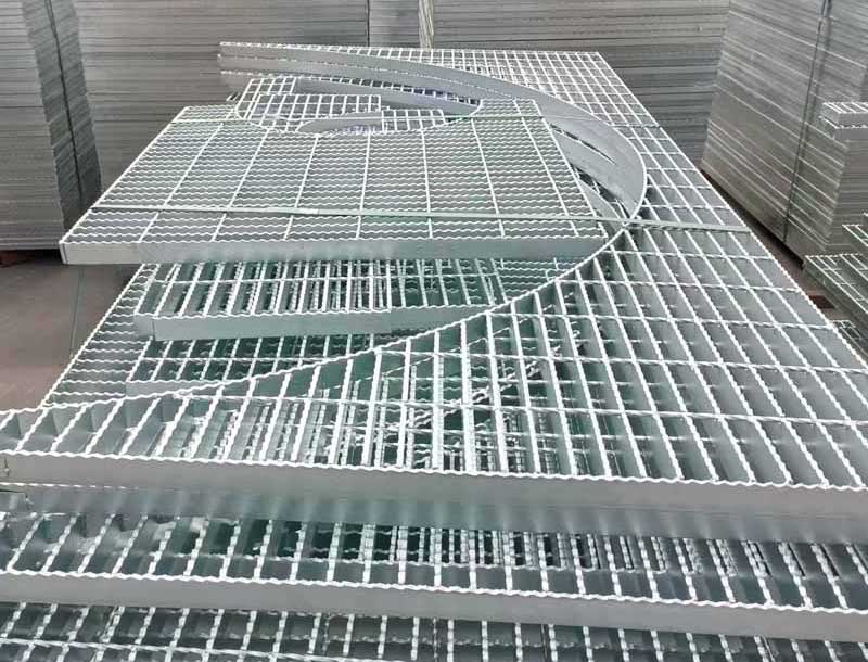
Carbon steel grating may require an appropriate protective treatment depending on the service environment.
Senfa’s current technical specifications identify hot-dip galvanized, painted, and untreated configurations among the available surface conditions.
The selected treatment should reflect where the panel will operate.
Outdoor locations, wet areas, process environments, and indoor dry spaces may create different exposure conditions.
The fabrication sequence also deserves attention.
Cutting, welding, edge reinforcement, and other major fabrication steps should be coordinated with the final surface treatment so that the completed panel has a consistent protective condition.
The specification should clearly identify:
- Required finish
- Environmental exposure
- Areas requiring fabrication
- Cutouts
- Edge treatment
- Field-modified locations
Surface protection should be considered at the design stage rather than added as an isolated final step.
9. Load Conditions and Deflection
A grating specification should clearly identify how the panel will be loaded.
This is more useful than simply describing the area as pedestrian, industrial, or heavy duty.
Important load conditions can include:
| Load Condition | Typical Source |
|---|---|
| Uniform load | People or materials distributed across a platform |
| Concentrated load | Equipment feet or localized machinery |
| Wheel load | Carts or mobile equipment |
| Permanent load | Fixed components |
| Repeated load | Regular equipment or personnel movement |
Load location also matters.
A concentrated force near the center of a span can affect the panel differently from a similar load close to a structural support.
Deflection should also be reviewed.
A panel may remain structurally intact while moving more than is desirable for a platform, walkway, or equipment route.
For this reason, load resistance and service stiffness should both be considered when determining the final specification.
10. Fabrication Details and Drawings
A written specification alone may not fully communicate complicated industrial layouts.
Platforms and walkways often include:
- Pipes
- Columns
- Equipment bases
- Valves
- Cable routes
- Stair openings
- Removable areas
- Structural braces
Drawings should show how the grating fits around these elements.
Important fabrication information includes:
- Panel marks
- Panel dimensions
- Bearing bar direction
- Cutout dimensions
- Banded edges
- Support lines
- Removable sections
- Fixing locations
Cutouts are particularly important because removing a bearing bar can alter the load path within the panel.
Large openings may require additional framing, reinforced edges, or a revised panel division.
Accurate drawings help move these decisions from the installation site into the design and fabrication stage, where they can be evaluated more systematically.
Why Bearing Bar Direction Must Be Specified
A specification should always identify bearing bar direction.
The bearing bars normally span between structural supports and form the primary load path.
If a rectangular panel is installed after being rotated 90 degrees, it may still fit physically while no longer matching the intended structural arrangement.
This is particularly important for platforms and walkways where several panels have similar dimensions.
Clear panel marks and installation drawings can help prevent orientation errors.
Bearing bar direction should therefore appear consistently on fabrication drawings, layout plans, and installation information.
Specifying Platform Grating
Industrial platforms often combine several different loading conditions within one structure.
A platform may contain pedestrian routes, equipment access areas, machinery openings, stairs, and removable maintenance sections.
The selected platform steel grating should therefore be specified according to support span, bearing bar dimensions, spacing, load conditions, panel layout, and equipment positions rather than from one overall platform dimension.
Senfa’s current platform product data includes bearing bar options from 20 × 3 mm upward, multiple bearing bar spacings, multiple cross bar spacings, and extended panel lengths, illustrating the number of variables involved in a platform configuration.
Equipment areas deserve particular attention because machinery feet can create concentrated loads that differ from normal pedestrian traffic.
Platform specifications should therefore identify high-demand areas rather than assuming that every panel experiences the same conditions.
Specifying Walkway Grating
Walkways place greater emphasis on pedestrian movement and continuous access.
Important specification items include:
- Walking width
- Support span
- Bearing bar direction
- Opening pattern
- Surface profile
- Drainage
- Panel joints
- Fixing arrangement
Where maintenance carts or other wheeled equipment use the walkway, wheel dimensions should also be reviewed.
Narrow wheels can interact differently with the grating openings than normal footwear.
Outdoor walkways may additionally require attention to moisture, environmental exposure, and contamination.
The specification should reflect the actual operating route rather than describing the grating only as an industrial walkway.
Specifying Drainage Grating
Drainage applications require the structural and hydraulic functions of the grating to work together.
The panel needs enough open area for water to pass through while remaining suitable for the traffic above it.
Important specification details include:
- Trench width
- Clear span
- Supporting frame
- Panel dimensions
- Bearing bar direction
- Opening size
- Load condition
- Surface configuration
- Removal requirements
Where vehicles or equipment cross a drainage channel, wheel loads can become a critical consideration.
The surrounding frame should also be specified because the grating cannot perform reliably without suitable edge support.
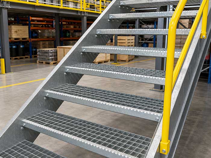
Specifying Stair Treads
Stair grating requires additional dimensional information compared with a general floor panel.
The specification may need to identify:
- Tread width
- Tread depth
- Bearing bar direction
- Surface profile
- Front-edge configuration
- Side fixing arrangement
- Stair support
- Environmental exposure
Stair treads experience repeated foot loading, particularly near the front portion of the tread.
Outdoor stairs may also be exposed to water or debris, making drainage and surface condition important.
The tread specification should therefore coordinate both structure and walking conditions.
Standard Dimensions and Project-Specific Requirements
Standardized dimensions can simplify fabrication where the structural system follows regular spacing.
However, many industrial projects contain irregular geometry.
Equipment, pipes, columns, trenches, walls, and access routes can make project-specific dimensions necessary.
A good specification should distinguish clearly between standardized parameters and dimensions that must follow the project drawings.
This reduces confusion during fabrication.
It also prevents a common problem where a nominal panel size is assumed to fit a structure without verifying the actual support arrangement.
Tolerances and Installation Clearance
Dimensional tolerances should be considered during specification development.
Fabricated steel structures and grating panels cannot be treated as having absolutely zero variation.
Practical installation clearance may therefore be necessary between panels and surrounding structural elements.
However, excessive gaps can affect walking conditions and alignment.
The project should balance:
- Fabrication tolerance
- Structural erection tolerance
- Panel clearance
- Joint consistency
- Maintenance access
Large platforms also need to consider tolerance accumulation.
A small dimensional difference repeated across many panels can create a significant mismatch at the far edge of the installation.
Fixing Requirements
A steel grating specification should identify how panels are expected to remain in position.
Depending on the application, mechanical clips, fasteners, or suitable permanent attachment methods may be used.
The fixing method should consider:
- Removable panels
- Vibration
- Pedestrian traffic
- Wheeled equipment
- Environmental exposure
- Maintenance access
The specification should also show where fixings are located.
Leaving all fixing decisions until installation can create inconsistent results, especially on large platforms with multiple panel types.
Edge Banding and Reinforcement
Panel edges may require banding or reinforcement depending on the configuration.
Banding can help finish open bearing-bar ends, define panel boundaries, or support fabricated openings.
Cutouts around pipes or equipment may also require edge treatment.
However, edge banding should not automatically be assumed to replace structural support.
Large openings may still need additional framing beneath the grating.
The specification should identify where banding is required and how it relates to nearby supports.
A Practical Steel Grating Specification Checklist
Before fabrication, project teams should confirm that the following information is available:
| Specification Item | Confirmed Information |
|---|---|
| Material | Carbon steel or specified stainless grade |
| Bearing bar | Depth and thickness |
| Bearing bar spacing | Required center spacing |
| Cross bars | Type and spacing |
| Panel dimensions | Length and width |
| Clear span | Unsupported bearing distance |
| Surface profile | Plain or serrated |
| Surface treatment | Required protective condition |
| Load type | Uniform, concentrated or wheeled |
| Bearing bar direction | Shown on drawings |
| Cutouts | Dimensions and locations |
| Edge treatment | Banding or reinforcement |
| Fixings | Type and position |
| Panel marks | Installation identification |
| Removable areas | Clearly defined |
A specification that addresses these items gives design, fabrication, and installation teams a much clearer technical basis for the project.
Common Steel Grating Specification Mistakes
One common mistake is specifying only panel length and width.
These dimensions describe fit but provide little information about structural performance.
Another mistake is specifying a bearing bar size without identifying the clear span.
Other recurring issues include:
- Missing bearing bar direction
- Undefined load conditions
- No distinction between plain and serrated surfaces
- Incomplete cutout information
- Missing support details
- Unclear panel marks
- Mixing unit systems
- Ignoring wheel dimensions
- Undefined fixing locations
- Surface treatment selected without considering fabrication
Each missing detail increases the likelihood that assumptions will be made later.
A complete specification reduces those assumptions.
How Specifications Improve Fabrication Accuracy
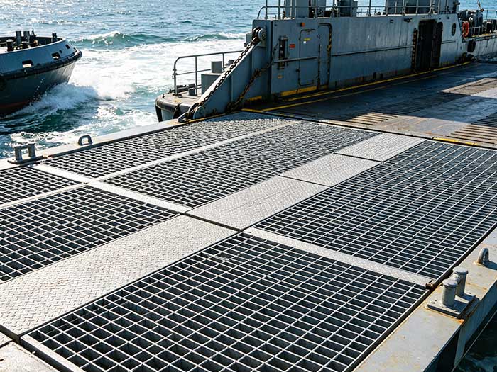
Clear specifications help the fabrication process follow the intended structural arrangement.
Bearing bars can be positioned according to the required spacing, cross bars can be installed consistently, and panel dimensions can be coordinated with the actual structural layout.
Cutouts and edge treatment can also be completed before the panels reach the installation site.
Senfa’s technical resources describe a manufacturing process that includes material preparation, bearing bar positioning, resistance welding or press-locking, edge reinforcement, quality inspection, and surface treatment.
Accurate specification information therefore supports each stage of fabrication rather than serving only as an administrative document.
Conclusion
Steel grating specifications should describe the complete panel system rather than only its outside dimensions.
Bearing bar depth and thickness, spacing, cross bar configuration, clear span, panel dimensions, material, surface profile, protective treatment, loading conditions, cutouts, edge treatment, and fixing requirements all affect how the finished grating performs.
The supporting structure and operating environment should be defined before the final panel configuration is established.
When specifications are coordinated with structural drawings, equipment layouts, application conditions, and fabrication requirements, the resulting panels are easier to manufacture, install, inspect, and integrate into the surrounding industrial structure.
FAQ
What information should steel grating specifications include?
Steel grating specifications should normally identify bearing bar dimensions, bearing bar spacing, cross bar configuration, panel size, clear span, material, surface profile, surface treatment, load conditions, cutouts, edge treatment, bearing bar direction, and fixing requirements.
Why is clear span important in a steel grating specification?
Clear span defines the unsupported distance between structural supports. It directly influences bending and deflection, so the same grating configuration may behave differently when support spacing changes.
Are panel dimensions enough to specify steel grating?
No. Panel length and width describe where the grating fits but do not define its structural behavior. Bearing bar dimensions, spacing, span, material, load conditions, and support arrangement are also necessary.
Should bearing bar direction appear on grating drawings?
Yes. Bearing bars normally carry the primary load between supports. Showing their direction helps ensure that panels are fabricated and installed in the intended structural orientation.
Can different areas of one platform use different grating specifications?
Yes. Support spans, equipment loads, traffic conditions, surface exposure, and maintenance requirements may vary across a platform, so different areas can require different grating configurations.